Wireless transmission
Table of contents
An innovative scheme for tuning antennas
Study on performance of antennas of mobile phones
A new scheme for the front-end of wireless receivers
Our experience in radio engineering
The performance of a portable wireless transceiver using a multiport antenna array for MIMO reception and/or transmission, for instance a user equipment (UE) of an LTE wireless network, depends on the impedance matrix seen by the radio-frequency signal ports of its receiver and transmitter. Unfortunately, three phenomena can degrade the performance of the transceiver:
- coupling between the antennas, which corresponds to nonzero nondiagonal entries in the impedance matrix, prevents correct matching with conventional receiver and transmitter front-ends;
- correlation between the different channels corresponding to the different antennas degrades the MIMO channel capacity, a phenomenon related to, but distinct from, coupling between antennas;
- the value of the impedance matrix of the multiport antenna array varies, in particular when the frequency of operation is changed, or when the electromagnetic characteristics of the volume surrounding the antennas are modified, for instance by a movement of the body of the user, an effect referred to as "user interaction", or "hand effect" or "finger effect".
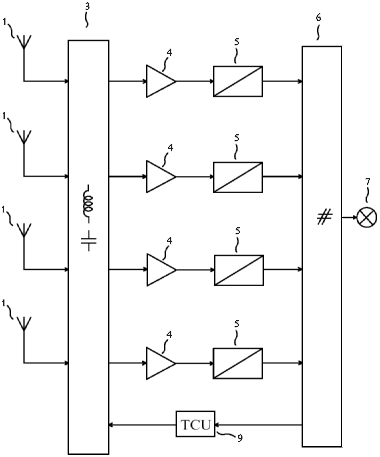
Fig. 1. A wireless receiver using multiple antennas simultaneously.
|
Excem has an R&D program aiming at innovative solutions to mitigate these causes of performance degradation. We have published several papers in this area. The MIMOmatch-B patent portfolio provides means for automatically compensating coupling between the antennas, correlation between the channels or variations in the impedance matrix of the multiport antenna array caused by a variation in the frequency of operation and/or by the user interaction. The MIMOmatch-B portfolio can therefore be compared to the United States Patent number 8,102,830 assigned to Samsung Electronics Co., Ltd, and to the United States Patent number 8,059,058 assigned to Sony Ericsson Mobile Communications AB.
For instance, the Fig. 1 shows an embodiment of an invention of the MIMOmatch-B portfolio, which consists of a receiver for radio communication using a plurality of antennas (1) and an antenna tuning apparatus (3) for simultaneously tuning the four antennas. The antenna tuning apparatus comprises adjustable impedance devices, each of the adjustable impedance devices having a reactance at a frequency, the reactance of any one of the adjustable impedance devices being adjustable by electrical means. Other buiding blocs shown in Fig. 1 are: four single-input and single-output low-noise amplifiers (4); four analog processing and conversion circuits (5); a multiple-input signal processing device (6) delivering a signal to a destination (7); and a tuning control unit (9). The multiple-input signal processing device delivers a tuning instruction. The tuning control unit receives the tuning instruction from the multiple-input signal processing device and outputs tuning control signals to the antenna tuning apparatus as a function of the tuning instruction.
|
|
For instance, the Fig. 2 shows an embodiment of another invention of the MIMOmatch-B portfolio, which consists of an antenna tuning apparatus for a multiport antenna array, which can be used in Fig. 1.
The antenna tuning apparatus shown in Fig. 2 comprises 4 antenna ports, 4 user ports, 10 adjustable impedance devices each presenting a negative reactance and having a terminal coupled to one of the antenna ports, 4 windings, and 10 adjustable impedance devices each presenting a negative reactance and having a terminal coupled to one of the user ports. All adjustable impedance devices are adjustable by electrical means, but they are represented with a variable capacitor symbol in Fig. 2. Any small variation in the impedance matrix of the antenna array, caused by a change in operating frequency or a change in the medium surrounding the antennas, can be compensated with a new adjustment of the adjustable impedance devices.
Companies interested in the possibility of implementing the MIMOmatch-B portfolio should contact us and have a look at
this section of the Tekcem web site.
|
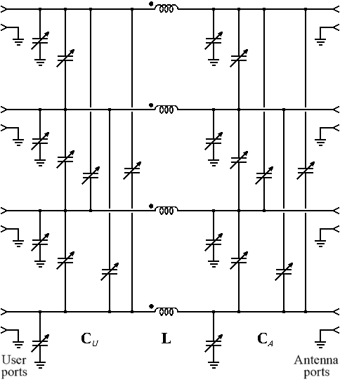
Fig. 2. An antenna tuner for simultaneously tuning four antennas.
|
The European Commission recently received a question from a Member of the European Parliament (MEP) mentioning investigations on the connection quality of mobile telephony in Denmark which have shown that:
- the coverage of cellular wireless networks is very nonuniform over this country, in terms of the ability to access the network (coverage) of a telecom operator, and of the achievable data rate;
- there are differences among telecom operators, as regards coverage and achievable data rate;
- there are differences in the sensitivity of mobile telephones, determined as the minimum electric field strength providing a specified downlink performance, in the presence of a human phantom head and hand.
|
The MEP considers that the antennas of popular mobile phones "are often unable to capture weaker signals" and asks the European Commission if it agrees "that consumers should be better informed through an EU labeling system on antenna strength" and if the Commission will "reconsider introducing requirements for a new minimum standard for mobile antennae in the European market".
Therefore the Commission has considered appropriate to have a deeper factual analysis of the current situation, and of the feasibility of the introduction of additional requirements and/or a labeling system before taking action in this area. Eurexcem was appointed by the European Commission to conduct this study. The title of the resulting report is "Technical support relating to performance of antennas of mobile phones — Final report — 2nd Edition — 28 January 2014". It can be downloaded here.
The European Commission has organized a workshop in Brussels on 10 April 2014. The results of Eurexcem's study have been presented for clarifying the situation. Possible ways to improve the performance of mobile telephone in the market have been debated with main stakeholders (mobile phone industry, mobile operators, consumer's associations, national authorities, etc).
The presentation of the report at the workshop of 10 April 2014 organized by the European Commission is available here.
|
 |
Wireless receivers for Multiple-Input and Multiple-Output (MIMO) and Single-Input and Multiple-Output (SIMO) wireless communication systems use several antennas forming a multiple-port antenna array. The performances of multiple-antenna radio communication systems are often assessed using the assumption of uncoupled antennas. This is an approximation, which will fail if the antennas are close to each other. The physical size of the antenna array being often limited by the application (e.g. in the case of portable transceivers), there is a need to take into account antenna coupling.
Fig. 3 shows the block diagram of a conventional receiver using multiple antennas, comprising 4 antennas (100), 4 bandpass filters (200), 4 low-noise amplifiers (300), 4 analog processing and conversion circuits (400) and a multiple-input signal processing device (550), whose output is connected to the destination (600). Matching of this receiver with the antenna array cannot be achieved because the impedance matrix of coupled antennas is not diagonal.
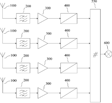
Fig. 3. Front-end of a conventional 4-antenna wireless receiver.
|
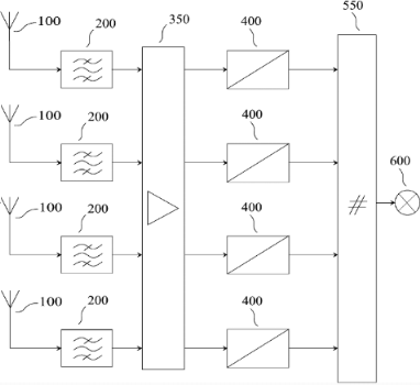
Fig. 4. MIMOmatch-A front-end using an array of 4 antennas.
|
Our new scheme for the front-end of wireless receivers using several antennas uses a single multiple-input-port and multiple-output-port (MIPMOP) low-noise amplifier (LNA) instead of multiple independent single-input-port and single-output-port LNAs in a conventional design. Such a MIPMOP LNA may provide hermitian matching with the multiple-port antenna array. In this case, maximum power transfer occurs. Detailed information on such a design has been provided in a published paper B68. An essential feature is that a low-noise MIPMOP amplifier requires no added circuit element compared to independent LNAs.
Fig. 4 shows the block diagram of a wireless receiver using a front-end disclosed in the MIMOmatch-A patent portfolio, comprising a MIPMOP low-noise amplifier (350), and the other blocks used in Fig. 3. As explained in B69, a good building block for this approach is the MIMO series-series feedback amplifier (MIMO-SSFA) initially introduced by Excem to obtain reduced crosstalk and echo in multiconductor interconnections using the ZXtalk method.
We refer to the wireless receiver front-end covered by the combination of our patent applications P30, P33 and P34 as a MIMOmatch-A front-end. The invention P41 is an improvement to P30 and P33. Note that the inventions P30, P41 and (to a lesser extent) P33 may also be applied to our ZXtalk method for the cancellation of echo and crosstalk in electrical interconnections.
Our published papers and Patent Cooperation Treaty (PCT) applications on the MIMOmatch-A can be reached in the Club Excem section of this web site.
The MIMOmatch-A patent portfolio has been sold in 2012 by Tekcem. For more information, please have a look at this section of the Tekcem web site.
|
Excem's senior research engineers have long experience in the design of wireless equipments, in radio science and in radio operation. They published several articles about the design of wireless receivers using multiple antennas B90 B69 B68. Regarding antennas, they published several papers on approximations for the fields near transmitting antennas B76 B72 B52 B49. They performed several studies concerning the reduction of interference in radio astronomy instruments like the Nançay radiotelescope, some of which led to published papers B42 B27 B25. They designed measuring instruments based on radio propagation, like the VIG3 systems presented in several articles B26 B19 B16 B14.
These research engineers are radio amateurs: Evelyne Clavelier is F1PHQ and Frédéric Broydé is F5OYE. The picture on the right shows the QSL card of F5OYE.
|
 |


